


Table of Contents: How to Find Sprinkler Valves
How to Locate Irrigation Valves
This article explains how to locate or find irrigation valves and wires using various kits. Irrigation system valve locating can sometimes be a challenge. Although a lawn irrigation system can run smoothly for years, it may be necessary to locate irrigation valves for maintenance or replacement of valves, valve parts or wiring.
To make it easier to find lost valves, the system installer might leave a diagram of the irrigation system, showing irrigation valve location. If not, lawn irrigation system valve location can be done by an irrigation professional, or by the homeowner. To find irrigation valves, the homeowner or contractor has several options, from digging up the lawn to using a reliable wire and valve locator.
What Are Sprinkler Valves?
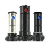
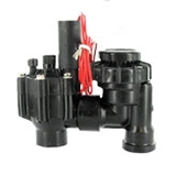
Sprinkler valves control the flow of water to the irrigation system. Each valve is responsible for one area, or zone, of the lawn irrigation system.
Automatic Irrigation Valves
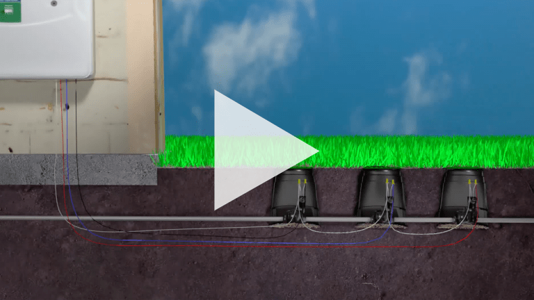
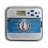
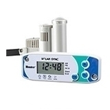
Automatic irrigation valves work by electricity. Wires lead from the irrigation controller, or timer, to each of the the valves. A solenoid on the valve receives electric signals from the main controller. To locate irrigation valves, one usually needs to determine which wire leads to which valve from the main controller.
What Is Inside The Valve?
Inside the valve is a diaphragm, or rubber plug. When the solenoid receives the signal from the controller, it tells the diaphragm to open, allowing water to flow through the pipes, or close, to shut off the flow of water. Damage to the wiring or solenoid can cause the valves to fail.
Lawn irrigation valves may be above ground, but often the irrigation valves are placed in a valve box and buried, making it difficult to find lost valves.
How to Find Sprinkler Valves
1. Estimate the Valve’s Location
The most cost-effective way to find irrigation valves is to estimate the irrigation valve location, and probe the soil gently in that area. This is not recommended unless one is sure that the lawn irrigation valves are protected by a valve box. Otherwise, probing the soil may result in damage to the solenoid, the valve wires or the irrigation system pipes.
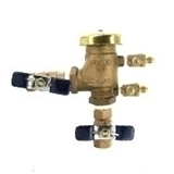
To find lost valves, picture the layout of the irrigation system. Note where the wires enter the ground from the main controller and visualize the path of the wire. A common irrigation valve location is near the corners of the house or main building, and/or just downstream of the backflow preventer. In most areas, it is illegal to install underground irrigation valves without an approved backflow preventer. Probe the likely location to a depth of about six to twelve inches. Listen for the hollow sound of the buried valve box. Dig carefully to avoid cutting the PVC irrigation pipes or damaging the wires.
While this valve location method is sometimes effective, the location of buried valves and valve boxes is an educated guess. Irrigation valves may also be in the middle of a zone, or in seemingly random places. Many a homeowner has dug up the entire lawn in an effort to find lost valves.
2. Check Local City Permits to Locate Irrigation Valves and Wires
Another way to determine lawn irrigation system valve location is to check with the local city permits department. Often, the irrigation system permit application includes an irrigation blueprint that indicates the valve’s location.
3. Follow The Wires
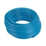
In automatic irrigation systems, a third way to find lost valves is to follow the wires from the controller. The wires run alongside the PVC pipe to the irrigation valve location. Dig small holes every ten feet to trace the wire. Be careful not to cut the wire.
It is helpful to note that buried irrigation valve wires rarely run under driveways. Sometimes this location method will find the buried lawn irrigation valves. Again, one can dig up a large portion of the lawn while trying to locate irrigation valves.
4. Use a Solenoid Activator or Chatter Locator
An alternative method of sprinkler system valve locating is to buy or rent a solenoid activator – also called a chatter locator. This device prompts a noise, or chatter, from the solenoid that allows a user to locate irrigation valves easier.
- Ask a helper to tap the valve wire onto the test post on the irrigation controller.
- Test at 5 to 10 second intervals, listening for a faint click from the solenoid or the sound of water as it starts rushing through the valve.
- Minimize background noise by testing at night or early in the morning.
- Turn on the zone in question, and note which sprinklers are the first to pressurize. These are the sprinklers closest to the irrigation system valve.
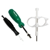
5. Use a Valve Locator
Using a valve locator is an accurate way to find lost valves without damage to your lawn or garden. Valve locators find lost valves by tracking the wires from the controller to the lawn irrigation system valve location. Comprised of a transmitter, a receiver, two lead wires, and a grounding stake, the valve locator transmits a beeping signal along the wire to locate irrigation valves.
How to Use a Valve Locator
The Armada Pro700 TechTracker Wire and Valve Locator is designed for professionals, but homeowners can also use the Pro700 to locate irrigation valves. As well as finding valves, the Pro700 detects damage to underground cables and wires and can help find the depth of a buried wire. The Armada Pro-700 has advanced electronic circuitry to minimize 50-60hz AC noise, producing a clear clean sound that makes it easier to find lost valves.

How to Use a Pro-700 Valve Locator to Find Valves
1. Install the Transmitter Batteries
- Open the transmitter case. The battery cover is located at the right-hand side of the transmitter unit.
- With the unit off, remove the two holding screws on the battery cover.
- Using eight “D” cell batteries, orient the batteries according to positive and negative polarity, and place the batteries in the holder.
- Once the batteries are installed, replace the cover and turn on the unit. The red power switch is located on the front of the transmitter.
2. Test The Batteries
- Push the red battery test button.
- A successful battery installation returns a reading of 8 or higher on the analog meter.
- If there is a poor response or no response at all, adjust the batteries to ensure a good connection.
- If still no response, be sure the batteries are good. For best results, use new, fully-charged batteries.
3. Install the 9V Battery in the Receiver
- Turn the Pro700 receiver over to locate the battery compartment
- Remove the two holding screws and lift the battery compartment cover.
- Connect the positive and negative terminals to the 9v battery, and place the battery in the compartment.
- Replace the cover and screws.
- Turn on the unit.
- Push the red battery test button on the underside of the Pro 700 R receiver.
- If the connection works, the analog needle on top of the receiver will move to the right, to an optimal reading of 10.
- If this doesn’t happen, check the battery.
4. Connect the Red Wire
WARNING: When the power is on, NEVER touch the red and black clips connecting the transmitter to the cable
- Touching the clips can result in serious injury or death.
- The controller, or timer, has several stations. Each station has a wire connecting to a different valve. Each valve is responsible for one zone of the sprinkler system.
- On the controller, find the wire leading to the desired zone valve. Disconnect this wire. As well, disconnect the common wire.
- With the transmitter OFF, plug the red lead into the red outlet on the transmitter. Connect the red lead to the wire to be traced.
5. Connect the Black (Ground) Wire
- Plug the black lead into the black outlet on the transmitter
- Clip the other end to the ground stake
- The ground stake must be inserted into the earth or soil.
- Never connect wires to the clock, and never use common grounds such as pipes or electrical grounds.
- The ground stake must be inserted into the soil, independent of the rest of the system. Otherwise, the valve locator will not work properly.
- If the controller is inside, it may be necessary to run an extension wire from the black lead to the ground stake.
- Use a length of insulated copper wire. On the extension wire, strip the insulation casing from the ends, leaving up to two inches of exposed wire.
- Clip the black lead to one end.
- Wrap the other end around the ground stake, and insert the ground stake into the soil outside.
- Be sure to push the ground stake all the way into the earth.
6. Test the Transmitter
- Turn on the Pro 700 transmitter
- Increase power until a reading between 4 and 8 appears.
- If the reading doesn’t register above four, turn the unit off.
- Retry Step #5, above.
- Poor grounding may be the result of soil conditions.
- Moist, earthy soil has better conductivity than dry, sandy soil. Moisten the grounding area if necessary.
- If results are consistently below four, re-test the batteries and replace if necessary.
7. Test the Receiver
- The power and volume knob is on the front of the Pro 700 receiver.
- Turn on the receiver. Make sure the transmitter unit is also powered on. Bring the receiver near the Pro 700 transmitter.
- The receiver is working properly if it emits a beeping sound.
- A high-pitched tone means the user is too close to the receiver, or that the batteries are low.
- A fading signal is also a sign of low battery power.
- The receiver comes with optional headphones, but it also has an external speaker. The headphone jack is on the underside of the receiver.
- The volume control regulates the loudness of headphones and/or the speaker.
- The analog meter, on the front of the receiver, shows the reception strength of the signal.
8. Find the Null Principle
- Make sure the transmitter and receiver are both on.
- Point the receiver toward the ground, and sweep the unit gently from side to side.
- Listen for the beeping sound.
- To the immediate right and left of the cable, the signal increases in volume. However, once the receiver is directly over the wire, it returns almost no sound at all.
9. Locate the Valves
- To locate irrigation valves, follow the null. Begin where the wire enters the ground.
- When nearing a valve or solenoid, the audible signal expands into an area roughly two to four feet in diameter.
- Since this is the irrigation valve location, the signal will usually not continue past this area. Sometimes, the cable may lead to more valves further on.
- If necessary, continue past the first valve to check whether other valves are also located on the wire.
How to Use the Pro 700 to Find Damaged Wire in Your System
To locate wire breaks or severe wire damage:
- The Pro 700 also locates wire breaks or severe wire damage.
- Set up the unit as if tracing wire to find lost valves.
- Do not adjust the receiver level above 10.
- A drop in signal level may not be apparent if the meter reads over 10, or is pegged hard to the right.
- A traced wire will emit a signal along the entire path of the cable. In the case of a break, the signal will stop at the break.
- A nick or damage to the wire will cause an audible drop in the signal level.
- The analog meter on the receiver will also show a drop in signal level. The more damage to the wire, the more the signal will drop.
- With practice and expertise, even small nicks in wiring can be located.
Note: Slack loops of wire left underground during installation can cause an increase in signal even if there is no damage to the wires.
How to Find the Depth of a Wire
- First, locate the path of the wire.
- Mark the ground above the path.
- Stand to the left or right of the path. Hold the receiver at a 45-degree angle, pointing toward the wire.
- Move the receiver slightly to find the angle that returns a null signal. Make a mark at the spot.
- The distance between the two marks is the approximate depth of the wire.
How to Find Irrigation Valves Using the Armada Pro-300
The Armada Pro-300 Wire and Valve Locator is ideal for smaller wired systems. Designed for contractors and homeowners who want to find irrigation valves and wiring problems, the Pro-300 is easy to use and offers high-performance results.

1. Install the Batteries in the Transmitter
- To install the eight “C” cell batteries, open the transmitter case.
- The battery compartment is located at the upper center area of the transmitter.
- Remove the five holding screws and open the battery compartment.
- Orient the batteries according to positive and negative polarity, and put the batteries in the compartment.
- Replace the battery cover.
2. Test the Transmitter
- Turn on the transmitter.
- The power switch is located on the front of the unit.
- There is a red LED on the upper front part of the transmitter. When the batteries are installed and the unit is ready, the red light will blink dimly.
- If not, adjust the batteries. Be sure the polarities are correct and the connection is good.
- If nothing happens, check that the batteries new and fully charged.
3. Install the Battery in the Receiver
- The receiver uses one 9v alkaline battery. The battery compartment is on the back of the Pro 300 receiver.
- Remove the battery compartment cover, and install the battery, taking care to properly connect the positive and negative terminals.
- Replace the cover.
4. Connect the Red Wire
- On the controller, disconnect the common wire, as well as the station wire of the valve to be traced.
- With the transmitter off, connect the red lead to either the common wire or the station wire.
5. Connect the Black Wire
- Connect the black lead to the ground stake. Insert the ground stake into the soil outside.
- Never connect wires to the clock, as this can cause damage to the clock.
- Do not use common grounds, such as pipes or electrical grounds.
- The ground stake must be placed in the earth and must be independent of the sprinkler system itself. Otherwise, the Pro 300 will not work properly.
6. Test the Connections
- Turn on the transmitter.
- Now, the LED should blink brightly. The better the ground connection, the brighter the light will blink.
- A good ground is important for effective sprinkler system valve locating.
- Soil conditions affect the unit’s ability to find lost valves. Moist soil is better for conductivity. Dry, sandy soil can make grounding more difficult. If desired, moisten the grounding area.
7. Adjust the Settings
- After connecting and testing the Pro 300 transmitter, turn on the receiver.
- The volume knob on the side of the receiver controls the power. Put the receiver near the operating Pro 300 transmitter.
- If the receiver is working properly, it emits a beeping sound. A high-pitched tone means that the user is too close to the receiver, or that the batteries are low. A fading signal also indicates low batteries.
- Adjust the signal volume using the volume knob on the side of the receiver.
- With both the receiver and transmitter powered on, let the receiver antenna dangle a few inches above the ground.
- Move it gently from side to side. Listen for a beeping signal. The closer the receiver comes to the cable, the louder the signal will be.
How to Find Sprinkler Valves Using the Pro-300 Null Principal
- The Pro-300 can find irrigation valves by operating on the null principle.
- To the left and right of the cable, the receiver emits a steady signal. Directly above the cable, the signal disappears. This is the null or absence of signal.
- By following the null, the user can trace the wire or cable directly to the buried valves.
- Too high a volume will overpower the null signal.
- If the null is not apparent, turn the volume down.
How to Use the Armada Pro-300 Valve Locator to Find Solenoids and Valves
Each valve controls a specific zone of the lawn irrigation system with a wire connecting the valve to the controller. Ideally, the zones are marked on the controller or on the wires themselves.
- Determine which wire connects to the valve to be located.
- Using the null principle, follow the wire.
- When the unit finds the irrigation valve location, the signal expands into an area about two to four feet in diameter. This indicates the presence of an underground valve or solenoid.
- Unless the wire connects to other valves further on, the signal will end here.
- In some cases, one might continue past the first valve, to locate other valves if they are on the same wire.
- Dig carefully to unearth the valve box and the underground valves.
How to Use the Armada Pro-300 Valve Locator to Find Wire Faults or Damage
The Pro 300 can also locate wire breaks or damaged wiring. The setup is the same as above except the difference is in the reception of the signal. A break in the wire causes the signal to stop at the point of the break. Damage to the wire causes a drop in signal, but the signal will not necessarily stop. Minor damage does not produce enough of a response, and cannot be located with the Pro 300. Practice and experience will help the user to operate the unit to maximum effect. If the LED light is weak or absent, be sure the cable or wire is properly grounded. If the signal can’t return to the ground stake, the location attempt will fail.
How to Find Irrigation Valves Using the Tempo 521A Wire and Valve Locator
The Tempo 521A Wire and Valve Locator is designed for superior performance in sprinkler system valve locating. For professionals or homeowners, the Model 521A has proven reliability in finding lost valves, locating damaged underground wires or finding the depth of a wire, even on higher resistance wire paths.

1. Install the Batteries
- With the transmitter OFF, open the battery compartment, located on the upper front area of the transmitter unit.
- Install the required eight “D” cell batteries. Be sure the batteries are oriented to the correct polarity.
- Turn the selector knob to the “Battery Test” position. The meter should read between eight and ten.
- The receiver uses one 9V alkaline battery.
- Open the battery compartment on the receiver.
- Insert the battery, taking care to properly align the positive and negative terminals.
2. Test the Unit
- Ensure that the 521A transmitter is at optimal signal strength.
- Connect the red and black leads together, and turn on the transmitter.
- Turn to selector knob to #5 and watch the meter needle.
- The needle should give a reading of at least 10. If not, check that the batteries are properly installed, and that they are fresh and fully charged.
3. Connect the Red Wire
- On the controller, find and disconnect the wire leading to the valve to be located. With the transmitter off, connect the red lead to this wire.
4. Connect the Black (Ground) Wire
- Clip the black lead to the grounding stake provided.
- The ground stake must be inserted into the soil outside. If the controller is inside the building, it may be necessary to run a wire from the black clip to the outdoors.
- To do this, use insulated copper wire.
- Remove the insulation casing from both ends of the wire.
- Clip the black lead to one end.
- Wrap the end of the extension wire around the ground stake. Do not use a common ground, such as electrical grounds or water pipes.
- If the ground stake is not outside, the grounding will be bad, the signal will not transmit properly, and the unit will not work.
5. Adjust the Settings
- Turn on the transmitter.
- Begin rotating the selector knob clockwise. Once the meter needle leaves the “Battery Test” position and reaches #1, it will drop to near zero. The needle will rise slightly each time the output increases.
- When the meter reads between four and eight, the transmitter is at peak efficiency.
- If the reading won’t go above four, the grounding is insufficient.
- Check that the black lead is properly attached to the ground stake (or, if using an extension wire, that the extension hasn’t slipped).
- Soil condition can also affect the efficiency of the unit. Damp, earthy soil conducts a signal much better than dry, sandy soil. Moisten the soil around the ground stake to improve conductivity.
6. Test the Unit
- The receiver has an external speaker, so the headset is optional. If using the headset, plug it into the receiver.
- To test the unit, turn the receiver on and point the antenna or probe end toward the transmitter.
- The unit should generate a pulsing tone, which can be heard through the headset or the external speaker.
- If the receiver battery is low, or if the headset cord is too close to the receiver, the unit will emit a high-pitched signal.
How to Find Sprinkler Valves Using the Tempo 521A Null Principal
To find lost valves and buried wires, the Model 521A Valve and Wire Locator operates on the null principle. When the receiver is immediately to the left or right of a buried wire, it emits a strong beeping signal. Directly over the wire, the signal falls off. This is the null, or absence of signal. To trace a wire to the lawn irrigation system valve location, follow the null.
Using the 521A to Find Solenoid Valves
If the solenoid is good, and the wires are intact, irrigation valve location is fairly easy.
- Once the red and black leads have been connected, and the unit is properly grounded, turn on the transmitter.
- Adjust the signal output to the highest level.
- Starting at the clock, begin tracing the path of the wire to be located.
- Move the receiver gently back and forth over the ground, and follow the null.
- When the receiver passes over a solenoid valve, the null disappears and the signal becomes more intense. This is the irrigation valve location.
How to Use the Tempo 521A to Check for More Irrigation Valves
Even thought the null may end there, sometimes there are additional valves along the same wire. To locate more irrigation valves, check for a null leading away the area of the valve. If there is more than one hot spot, or irrigation valve location, mark each spot. Go back to the transmitter, and turn it off. Take the black lead from the ground stake. Connect it to the common wire at the controller. Turn the transmitter back on, and turn the selector knob to its highest reading.
With the receiver, go back to the first valve location. Bring the tip of the receiver antenna to touch the ground at the center of the hot spot. Set the sensitivity knob to around mid-scale.
Go to the second spot. Without adjusting the sensitivity knob, touch the antenna to the ground to check the signal strength. Repeat at each hot spot. The strongest signal indicates the valve located on the wire to which the red clip is attached.
How to Use the Tempo 521A Valve Locator to Find a Fault or Break in the Wire
- First, decrease the sensitivity of the receiver when pointing it off to either side of the null. The signal intensity will change.
- Do not allow the meter to peg, or to move above a reading of 10. To locate a wire, it must have a path to ground.
- Often, buried wires have this path due to imperfections, nicks, or bad splices. If not, ground the remote end of the wire.
- Locate the end of a damaged wire by following the path of the wire until the null disappears and the signal increases.
- No null will be present beyond the hot spot. Back up until the null appears, indicating the end of the broken wire.
- Find larger nicks in the cable by tracing the path of the wire in the same way.
- When a nick is present, the signal along the sides of the null becomes weak. The signal will strengthen near the nick, then drop off to a low reading just past the nick.
- To pinpoint the location more accurately, find the spot where the last strong signal occurs along the side of the wire path. Point the receiver tip at the ground, about six inches to either side of the null.
- Make sure to adjust the sensitivity knob so that the meter reads slightly below 10.
- Keeping a 6-inch distance from the null, move the receiver down the path. Watch the meter reading. Past the open wire or nick, the meter will drop sharply.
How to Use the Tempo 521A Valve Locator to Determine the Depth of the Wire
- First, locate the path of the wire.
- Mark the ground immediately over the path.
- Step to the side, and turn the receiver towards the path at a 45-degree angle. Slowly move the receiver away from the path, keeping the 45-degree angle. Stop when the null appears.
- Mark this spot as well.
- The distance between the two marks indicates the approximate depth of the wire.