


How To Divide Sprinkler Systems Into Zones
Step 1:
- Get some grid paper
- Choose a scale (e.g. 1 square equals 5 feet)
Step 2:
- Draw out your property (grid has been removed for clarity)
- Be as accurate as possible with layout and measurements (don’t forget to include all landscape features)
Step 3:
- Divide the yard into areas that you would like to water at the same time (e.g. Front Yard, Backyard, Flower Beds)
- Green = Backyard
- Lite Green = Front Yard
- Red = Flower Beds
Step 4:
- Plan out where each sprinkler head will be placed
- Use the sprinkler radii as a guide for sprinkler placement (remember head-to-head coverage)
- There are a lot of free design services that will help you with this step (check online)
Step 5:
- Break down the areas into smaller groups of sprinkler
- NOTE: Never mix rotors and sprays in the same group
Step 6:
- Using the chart below, write out the gallons per minute (GPM) for each sprinkler
| Spray Pattern | Rotors | Sprays |
| Quarter Circle | 2-GPM | 1-GPM |
| Half Circle | 4-GPM | 2-GPM |
| Full Circle | 8-GPM | 4-GPM |
| Standard Pressure | 50 PSI | 30 PSI |
- Add together all the GPMs you’ve written down for each sprinkler and get the total GPM
Step 7:
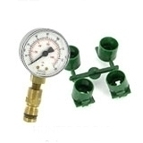
- Determine the size of your water service line and meter
- With that information, determine the maximum GPM that your line can supply to the system (water capacity charts are available online)
- In this example, the maximum that this system can use is 18 GPM
Step 8:
- In this example, three of the groups use more than the maximum 18 GPM (see circled GPMs)
- Break down any groups using too many GPMs into smaller groups that do not exceed the available flow rate (in this example, the available flow rate for each group is 18 GPM)
- Each of these new groups will be a single zone in your system (sprinkler heads have been color-coded to represent individual zones)
Step 9:
- Now that the zones have been laid out, we are ready to plan the piping.
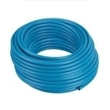
- Using the flow rate chart, select a pipe size that allows for the flow required by your system (usually 1” piping is recommended for best results).
- When connecting to the water supply line, use at least Schedule 40 pipe, nothing thinner.
- Max Flow for PVC pipe
| 3/4” Class 200 | ——————- | 10-12 GPM |
| 3/4” Sch. 40 | ——————- | 7-9 GPM |
| 1” Class 200 | ——————- | 16-20 GPM |
| 1” Sch. 40 | ——————- | 12-15 GPM |
| 1-1/4” Class 200 | ——————- | 26-32 GPM |
| 1-1/4” Sch. 40 | ——————- | 22-27 GPM |
- In this example, 1-1/4” Sch. 40 PVC pipe will allow us to pull the 18 GPM needed for our system
When planning your system, don’t forget:
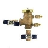
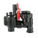
- Backflow Prevention
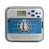
- Controller/Timer
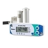
- Rain Sensor
Step 10:
- We can now lay the main 1-1/4” Sch. 40 pipe
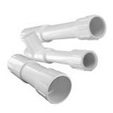
- Run the pipe from the meter to the backflow and from the backflow to the rest of the system
- Note: the white line indicates the water pipeline to the house
- Draw in the placement of the valves
- Best practice is to place each valve as close as possible to the center of its respective zone
- In each zone, we will use 1” Class 200 PVC after the valve (this will still allow adequate flow)
- Because the line will not be pressurized all the time, a thicker pipe is not needed
- Tip: try to lay the zone piping in the trenches you already made for the mainline
Finished! Your design is now complete, and you are prepared to install your system.