


From Mounting To Controller Connection
It’s easy to install a Hunter Mini Weather Station. And this article is going to provide the necessary instruction and wiring information.
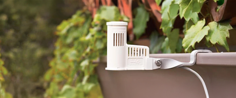
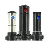
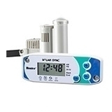
The three sensors combined on this product are for wind speed, rainfall, and temperature (near-freezing conditions). Each sensor operates independently of the other; therefore, any or all of them may be switching at a given moment. See the separate product installation instructions for details on the Mini-Clik, Wind-Clik or Freeze-Clik operation and settings. However, use only the “mounting” details contained on this sheet.
Mounting
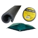
The weather station is designed to mount on a post of 2″ PVC pipe. However, any combination of pipe and fittings can be used to tailor an installation. The enclosed “reducer” fitting has two purposes: 1) It allows for the use of 1/2″ PVC pipe for shorter mounts, and 2) Screwed down onto surface (wood post or deck), it acts as a base for the weather station to fit onto. Important: For most accurate temperature sensing, rotate the weather station so the thermostat portion points north.


Wiring To The Hunter SRC Controller
The Mini-Weather Station connects directly to the SRC irrigation controller. As a result, this allows you to easily override the sensor by using the RUN (BYPASS SENSOR) position on the dial.
- Route the wires from the Mini-Weather Station up through the same opening used for valve wiring.
- Connect one wire to the RS terminal and other to the C terminal (See Figure 1).
- Connect the valve common to the RS terminal.
Wiring To The Hunter Pro-C Or ICC Controller
The Mini-Weather Station connects directly to the Pro-C or ICC irrigation controller. Therefore, this allows you to easily override the sensor by using the Sensor switch on the front panel.
- Remove the jumper from the two “SEN” terminals.
- Route the wires from the rain sensor up through the same conduit opening used for valve wiring.
- Connect one wire to the terminal labeled “SEN” and then connect the other wire to the other “SEN” terminal (See Figure 2).
Other 24 VAC Controllers
All three sensors are electrically connected in a series, so only two wires need to be used to connect to the irrigation controller. Use the green and silver (clear insulation) wires to hook up to normally-closed logic situations. Follow the wiring instructions in any of the separate sensor manuals, or place the two wires on the controller’s “sensor input” screw terminals if available (See Figure 4). For controllers with normally-open sensor inputs (most Toro models), please consult factory. Note: For extending wires, use wire 18AWG or heavier.