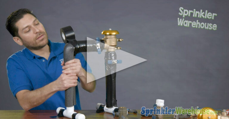
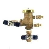
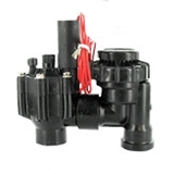


Pressure Vacuum Breaker Assembly Installation
The irrigation system site plan will indicate the pressure vacuum breaker installation location. It should be as close as possible to the isolation valve and within a few inches of a trench leading to the zone control valves.
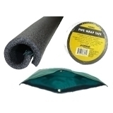
Before installing the pressure vacuum breaker assembly, run the supply pipe to the location of the assembly in accordance with the site plan and, if necessary, use an elbow to turn the supply line vertically and upward. Glue along the riser into the elbow. This riser will be cut to the correct height in the next step.

Determine the minimum installation height. Find the highest outlet on the system. In a relatively flat landscape, this is likely to be at the top of a shrub watering riser or sprinkler head. It may be necessary to drive a stake where the riser will be and mark the height of the outlet. Use a laser or string level to find and mark this height on the pressure vacuum breaker assembly riser. On the pressure vacuum breaker assembly riser, measure up twelve inches and place a second mark. If the riser isn’t tall enough, extend it with a coupling. This mark represents the height of the vertical center of the outlet valve.
If The Assembly Has Built-In Unions Between The Shutoff Valves And The Interior Body:
- Line up the pressure vacuum breaker assembly, centering the outlet at the height of the second mark and the inlet is downward. Place a third mark on the riser at the bottom of the pressure vacuum breaker assembly inlet valve. Cut the riser on the third mark.
- Open the isolation valve to flush out any foreign material in the supply line. Close the isolation valve, and dry the end of the pipe. Use a towel to wick water down if necessary so that the top few inches are empty and dry.
- Using pipe sealant compound, tighten PVC Slip X MIP adapters into the inlet and outlet shutoff valves on the assembly. Position the assembly on the riser so that the bonnet is on top. Turn the assembly so that later shelter cover can be installed in the most visually satisfactory position. Glue the inlet adapter onto the riser working quickly to avoid damaging internal parts.
- Cut a three to four-inch length of PVC. Glue an elbow onto one end, and then glue the other end into the outlet adapter pointing the elbow downward. Measure, cut, and glue a length of pipe long enough to extend from the elbow to three inches above the bottom of the trench. Skip the following instructions for installing unions.
PVB Assembly Doesn’t Have Built-In Unions
Part One: PVB with built-in unions
- Measure the length of the union body not including connection hubs. Measure down from the third mark and place a fourth mark. Cut on the fourth mark to achieve minimum installation height.
- Cut the riser again four inches from the top, insert the union between the two pieces and glue it into place. Glue a Slip X MIP adapter to the top of the riser. Allow cooling. Separate the union, apply thread sealant compound, and tighten with a wrench.
- Open the isolation valve to flush foreign material from the supply line, close the valve, and dry the adapter. If water stands in the riser, loosen the union to drain, then retighten.
- Apply pipe sealant compound to the male adapter threads, then connect the inlet shutoff valve on the pressure vacuum breaker assembly to the riser so that the inlet is at the bottom and the bonnet is at the top. Loosen the union if necessary and turn the assembly so that later the cover can be installed in the most visually satisfactory position.
- Glue a short length of pipe, about four inches, into the second Slip X MIP adapter. Using pipe sealant compound, tighten the adapter into the outlet shutoff valve on the assembly.
- Glue an elbow, plumb and pointed downward, onto the supply line where it exits the assembly. Glue another four-inch pipe into the elbow.
Part Two: PVB with built-in unions
- Now its time to separate the second union. Then apply thread sealant compound to the threads, and reconnect hand tight. Glue the union onto the downturned supply pipe.
- Measure, cut, and glue a length of pipe long enough to extend from the elbow to six inches below ground level.
- Make sure everything is properly aligned and then wrench tighten the union connectors.
- With both unions and the assembly now installed, the next step is to provide a hose bibb.
- Glue an elbow, a six-inch length of pipe, and then a riser tee with a half-inch outlet (usually a 1 X 1 X 1/2 tee) onto the supply line.
- Measure, cut, and glue a length of pipe long enough to extend four inches above the ground into the vertical opening in the tee and then glue a male adapter on top. Allow to dry.
- Tighten an FIP hose bib onto the riser using thread sealant compound. This hose bib will be necessary to drain the system for winterization or repair.
- Glue a random short length of pipe (at least six inches) and then a Slip cap into the downstream lateral opening of the tee. This is temporary. Later you will cut this cap off to continue installing downstream supply pipe.
- You can do the installation with copper pipe and fittings if you have the soldering equipment and skill. Otherwise, PVC installed as described above is legal and adequate in most jurisdictions. When using copper pipe and fittings transition to plastic after the hose bib. Copper provides no advantages beyond this point.
Following the manufacturer’s instructions, test the assembly for leaks, then schedule an inspection if required.
NOTE: When Installed Outdoors, The Pressure Vacuum Breaker Assembly Must Be Enclosed. Removable Covers Are Usually Permissible. When Installed Indoors, Adequate Drainage Must Be Installed. Adequate Drainage Means All Water Will Safely Drain Away In The Event Of A Complete Assembly Failure.
The last step in the installation procedure is to put all printed materials in a safe easy-to-remember location along with other irrigation literature. You will need it in the future.
Pressure Vacuum Breaker: Maintenance
The only standard yearly maintenance procedure for a pressure vacuum breaker assembly is the annual system winterization routine. Even if the PBVA has a freeze protection relief valve, the system must be completely drained. The specific procedure for draining the system will depend on-site factors such as slopes, water source, and drain valve locations. Once the system drains, leave the test cocks on the PVBA halfway open. Some jurisdictions require an inspection when before reactivating the system in the spring.
Every five years all non-metallic internal components should be replaced.
Pressure Vacuum Breaker: Repair


Every backflow prevention device comes with written specifications, instructions, and part numbers. Put these in a safe place. You will need this information to make repairs. If it has been lost, obtain a copy from the supplier or search for one online.
The local code will determine who can test and repair the backflow prevention device. In most cases, if the homeowner is allowed to test and repair, an inspection by a state-certified blowout prevention inspector will be required before the unit is put back into service.
Before opening the pressure vacuum breaker assembly, close the isolation valve, the outlet shutoff valve, and the inlet shutoff valve in that order. Open test cock #2 to release pressure. Then remove the assembly cover.
One common cause of pressure vacuum breaker malfunction is debris in the system, particularly the poppet or check assembly. To clear debris, remove the bonnet screw, the bonnet assembly, and the poppet assembly. Look for debris–bits of grass, grains of sand, etc. If any is found, rinse parts, reassemble, and test. Otherwise, remove the retainer and check assembly. Keep parts organized and out of the turf. Again check for signs of debris. Partially open the isolation valve and then partially open the inlet shutoff valve to flush any debris from the line. Close the valves and rinse all parts with clean water only. Inspect each part for visible damage and replace it as necessary. Reassemble in reverse order and test.
When the assembly seems to be working properly again, close the isolation valve and arrange for an inspection if required before putting the irrigation system back in service.
Pressure Vacuum Breaker: Replacement

Replacing the entire pressure vacuum breaker assembly with a new one is a fairly simple process. Disconnect the assembly section at the unions, and duplicate the section using a new assembly, pipe, and fittings. Then reconnect, test for leaks, and call for an inspection.
It must be noted, though, that once the entire original pressure vacuum breaker assembly is discarded, any “grandfather” protection is probably lost. If pressure vacuum breaker assemblies have been proscribed locally since it was installed, it may have to be replaced with a new double-check valve assembly or reduced pressure assembly. Check with local authorities before replacing the entire assembly.