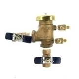
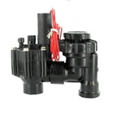
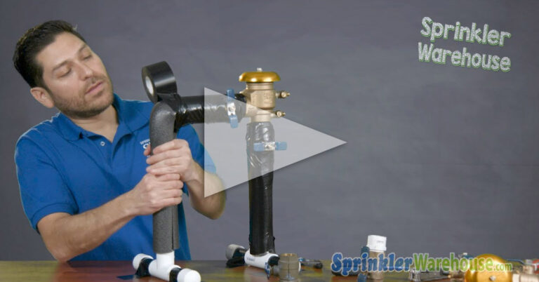
This article discusses underground and above-ground installations of a double-check valve assembly.
A Guide To Understanding The Double Check Valve Assembly
- Before installation, run the main irrigation supply line from the isolation valve to the vicinity of the DCVA valve box. Temporarily seal the end of the pipe to keep out soil and debris.
- Install a rectangular irrigation box in accordance with the local code. Dig a hole at least 30″ deep and 3″ larger at 18″ depth than the dimensions of the valve box. Center it with the trench. And fill it with enough drain rock to provide a flat surface 18″ below grade. Cover the rock with landscaping mesh before setting the rectangular valve box in place. Hold in place by packing soil on two sides away from the inlet and outlet holes. Pack the remaining two sides after installing the assembly.
- Cut inlet and outlet holes in the valve box as needed. The hole should be no more than 1/4″ larger in diameter than the pipe.
- Examine the double-check valve assembly to determine which end is the inlet and which is the outlet. Arrows stamped on the assembly indicate the direction of flows. Do not proceed until certain.
- Find the clearance from the interior of the valve box to the first fitting. Dry fit the assembly, unions, hose bib tee, and all connecting pipes. Measure the interior length of the valve box between the inlet and outlet holes. Subtract the assembly length from the interior length and divide the result in half. This is the distance from the interior upstream side of the valve box to the first fitting. Verify that there is enough clearance in the box for the ball valve handles in the open and closed positions. Adjust the distance from the side of the valve box if necessary.
- Run the supply line into the box and cut it to the length determined above.

If the DCVA has built-in unions between the Shutoff Valves and Interior Body:
- Open the isolation valve to flush the main supply line thoroughly. Close the isolation valve and dry the end of the pipe. Using thread sealant compound, tighten a Slip X MIP adapter into the inlet shutoff valve of the double-check valve assembly. Glue or solder the adapter to the supply line positioned so that the test cocks are on top.
- Tighten the second Slip X MIP adapter into the outlet shutoff valve. Glue or solder the connecting piece, a tee with a 1/2″ outlet turned upwards, and another length of pipe (long enough to exit the box) in line.
- Glue or solder a short riser into the tee and install the hose bibb on top of the riser positioned so that an air hose can easily be connected to the hose threads. Skip the following instructions for installing unions.
If the DCVA does not have Built-In Unions between the Shutoff Valves and Interior Body:
- It will be necessary to keep pipe sections as short as possible in this installation to fit everything in the valve box. Just remember that the shortest length of pipe must be double the length of the fitting hub plus one-half inch so that when the connection is complete some pipe will be visible.
- Glue or solder the first union to the main supply inside the valve box taking care to remove any thread sealant compound on the interior of the pipe and fitting.
- Open the isolation valve to flush the main supply line thoroughly. Close the isolation valve and dry the end of the union.
- Tighten both Slip X MIP adapters into the inlet and outlet shutoff valves. Wipe away any excess compound inside the fitting or valve.
- Separate the union. Apply compound to the threads and re-tighten hand tight. Glue or solder a short piece of pipe between the union and the assembly. Allow to dry or cool.
- Glue or solder a short piece of pipe into the adapter on the outlet shutoff valve and then the second union onto the end of the pipe. Separate the union, apply compound, and hand tightens.
- Glue or solder the connecting piece, a tee with a 1/2″ center outlet turned upwards, and another length of pipe (long enough to exit the box) in line. Glue or solder a short riser into the tee and install the hose bibb on top of the riser positioned so that an air hose can easily be connected to the hose threads.
- When the entire assembly is straight in line and the test cocks are properly positioned on top, tighten the unions with a wrench.
- Protect the open end of the supply with a temporary cap or plug. Seal any holes in the valve box from the outside with duct tape to keep dirt out, and pack soil around the valve box with a mallet.
- Following the manufacturer’s instructions, test the assembly for leaks. Then call for an inspection if required.
- Lastly, put all written materials that came with the double-check valve assembly in a safe place for future use.
DCVA- Above Ground Installation:
The steps for installing a double-check valve assembly overhead in an interior space are the same as for an inline (underground) installation except that access is provided differently, If the assembly is installed overhead, it should be located where nothing will be placed below it-no furniture, stacks of boxes, vehicles, etc.
A person should be able to enter the room or space and close the shutoff valves within a matter of seconds without stopping to move anything or locate a ladder. Also, if the backflow prevention device is located inside a dwelling, it’s a good idea to consult a local inspector regarding Americans with Disabilities accessibility standards.
To install the double-check valve assembly above ground outdoors:
- Run PVC from the isolation valve to the double-check valve assembly location indicated on the site plan. Open the isolation valve and flush the line thoroughly.
- Glue an elbow turned upward onto the supply line. Allow solvent cement to dry. Measure, cut, and glue a length of PVC long enough to extend from the elbow on the supply line to at least twelve inches above grade. The vertical pipe should be plumb.
- Prepare the double-check valve assembly. Tighten Slip X MIP adapters into each shutoff valve using thread sealant compound. Glue three-inch lengths of PVC pipe and then elbows turned down into each adapter. The assembly test cocks should be on top when the elbows are pointed down.
- Dry-fit the rest of the loop before gluing. Connect the elbow on the upstream (inlet) end of the assembly to the riser on the supply line. Cut, measure, and assemble a length of pipe extending from the downstream end of the assembly to the bottom of the trench leaving enough room for an elbow at the bottom. Add the final elbow and a six-inch length of pipe to continue the supply line on the downstream side of the double-check valve assembly. Once you have aligned all the parts and verified that they are plumb, disassemble the assembly and then reassemble it with glue.
- If the double-check valve assembly does not have built-in union connections, cut the vertical pipes on the inlet and outlet side about four inches below the assembly. Separate the unions, apply thread sealant compound, and hand tightens. Reconnect the double-check valve assembly to the loop by gluing the unions in place. With everything aligned properly, wrench-tighten the unions.
- With both unions and the assembly now installed, the next step is to provide a hose bibb. Glue a six-inch length of pipe, and then a riser tee with a half-inch outlet (usually a 1 X 1 X 1/2 tee) onto the supply line.
- Measure, cut, and glue a length of pipe long enough to extend four inches above the ground into the center opening in the tee, and then glue a male adapter on top. Using thread sealant compound, tighten a FIP hose bibb onto the riser. This hose bibb will be necessary to drain the system for winterization or repair.
- Homeowners may install the assembly using copper pipe and fittings if the homeowner has the soldering equipment and skill. Otherwise, PVC installed as described above is legal and adequate in most jurisdictions. If you use copper pipe and fittings, transition to plastic after the hose bibb. Copper provides no advantages downstream from the hose bibb.
- Following the manufacturer’s instructions, test the assembly for leaks, then call for a backflow inspection if required.
NOTE:
When installed outdoors, the double-check valve assembly must be enclosed. Removable covers are usually permissible. The last step in the installation procedure is to put all printed materials in a safe easy-to-remember location along with other irrigation literature. It will be useful in the future.
Maintenance:
- As part of the annual winterization and maintenance of the underground irrigation system valves: Close the irrigation system isolation valve. Blow out the lines. Open all the valves on the double check valve halfway and clean out any debris from the valve box.
- If the assembly is indoors, make sure access is still clear when you reactivate the system in the spring. Have the assembly tested and inspected in accordance with local code.
- Scheduling inspections just before reactivating the system in the spring will get the season off to a good start. Every five years, have internal non-metallic parts replaced and inspect internal metal parts for possible replacement. SprinklerWarehouse.com has replacement parts for all major brands of double-check valve assemblies.
Repair:
- Each double-check valve assembly comes with explicit instructions for maintenance and repair. Rubber components check modules, and seals can be replaced by a mechanically competent homeowner or plumber (if allowed by local code). Many jurisdictions require that any time the access cover is opened for any reason or the assembly is disconnected from the system, it must be tested by a state-certified backflow assembly inspector before being put back into service.
- Replacement is rarely ever necessary. Replacing the entire double check valve assembly with a new one is a fairly simple process. Disconnect the assembly section at the unions, and duplicate the section using a new double check valve assembly, pipe, and fittings. Then reconnect, test for leaks, and call for an inspection if required.
- It must be noted, though, that jurisdictions around the country have been proscribing double check valve assembly or specific installation configurations recently. Once the entire original double check valve assembly is discarded, any “grandfather” protection is probably lost.
- If double check valve assemblies have been proscribed locally since it was installed, it may have to be replaced with a new pressure vacuum breaker or reduced pressure assembly. Check with local authorities before purchasing a replacement double check valve assembly.


